| Board | TX GPIO | RX GPIO | RTS GPIO | CTS GPIO |
|---|---|---|---|---|
| ESP32C3 Official Hardware | 5 | 4 | 6 | 7 |
| ESP32C6 Official Hardware | 21 | 2 | 22 | 23 |
| SYS_ESP32_MODE | DroneBridge for ESP32 Mode | Encryption | Description | Notes |
|---|---|---|---|---|
| 1 | WiFi Access Point Mode | WPA2 PSK | ESP32 launches classic WiFi access point using 802.11b rates | Any WiFi device can connect. Can manage up to 10 WiFi stations/clients. |
| 2 | WiFi Client Mode | min. WEP | ESP32 connects to an existing WiFi access point. LR Mode supported | Encryption defined by access point. Multiple drones can connect to one AP and GCS. 802.11b rates |
| 3 | WiFi Access Point Mode LR | WPA2 PSK | ESP32 launches WiFi access point mode using espressifs LR mode | Only ESP32 LR Mode enabled devices can detect and connect to the access point. Data rate is reduced to 0.25Mbit. Range is greatly increased. |
| 4 | ESP-NOW LR Mode AIR | AES256-GCM | ESP32 is able to receive ESP-NOW broadcast packets from any GCS in the area and forwards them to the UART. Broadcasts to all GND stations in the area. | Connectionless protocol. Data reate is reduced to 0.25Mbit. Range is greatly increased compared to WiFi modes. Custom encryption mode for ESP-NOW broadcasts and protocol. |
| 5 | ESP-NOW LR Mode GND | AES256-GCM | ESP32 is able to receive ESP-NOW broadcast packets from any drone in the area and forwards them to the UART. Broadcasts to all AIR stations in the area. | Connectionless protocol. Data rate is reduced to 0.25Mbit. Range greatly increased compared to WiFi modes. Custom encrpytion mode for ESP-NOW broadcasts and protocol. |
| 6 | Bluetooth LE | TBD | Bluetooth LE (BLE) connection to your device. | The application (GCS) must explicitly support BLE connections. Use the DroneBridge BLE Bridge application to connect to your GCS. |
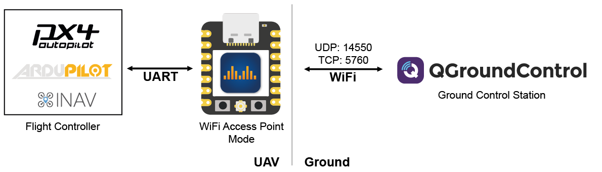
DroneBridge for ESP32 Wifi Access Point DroneBridge for ESP32 Wifi Client Mode ConceptMode Concept
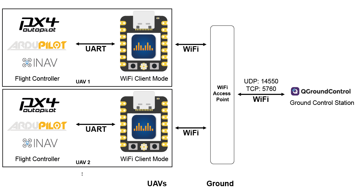
DroneBridge for ESP32 Wifi Client Mode Concept
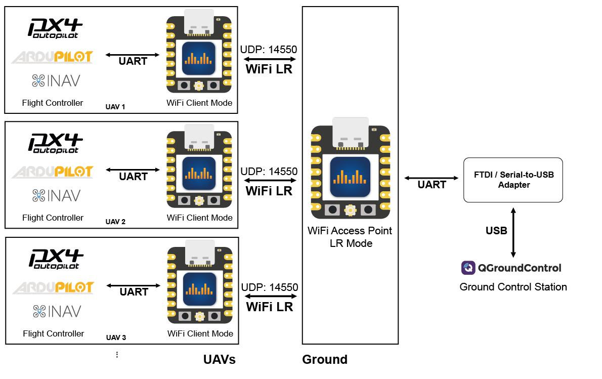
DroneBridge for ESP32 Concept for ESP32 WiFi Long Range Mode. Requires all parterns to use an ESP32 with LR mode enabled.
DroneBridge Bluetooth LE Bridge to connect ESP32 in Bluetooth LE Mode to ground control stations.
Betaflight BLE connection using DroneBridge Bluetooth Low Energy Bridge
| Web Parameter Name | MAVLink Parameter Name | Description |
|---|---|---|
| Mode | SYS_ESP32_MODE | Check the modes section |
| SSID | Cannot be configured via MAVLink | Specifies the name of the Wi-Fi network in access point and client mode. Up to 31 characters long. WiFi must be at least WEP protected. |
| Password | Cannot be configured via MAVLink | Wi-Fi access point or ESP-NOW password used for encryption. Min. 8 characters, max 63 characters long. WiFi must be at least WEP encrypted. |
| Channel | WIFI_AP_CHANNEL | Wi-Fi access point or ESP-NOW channel. |
| Gateway IP address | Cannot be configured via MAVLink | IP address you want the access point to have |
| UART TX PIN | SERIAL_TX_PIN | TX GPIO of the ESP32. If the pin matches the RX pin, the UART will not be opened. |
| UART RX Pin | SERIAL_RX_PIN | RX GPIO of the ESP32. If the pin matches the TX pin, the UART will not be opened. |
| UART RTS Pin | SERIAL_RTS_PIN | RTS GPIO of the ESP32. If the pin matches the CTS pin, flow control will be disabled. |
| UART CTS Pin | SERIAL_CTS_PIN | CTS GPIO of the ESP32. If the pin matches the RTS pin, flow control will be disabled. |
| UART RTS threshold | SERIAL_RTS_THRES | Threshold of hardware RX flow control to prevent FIFO overload. Set any number of bytes between 0-127. Best to leave at 64. |
| UART serial protocol | SERIAL_TEL_PROTO MSP/LTM = 1 MAVLink = 4 TRANSPARENT = 5 | Configures the parser. Set to transparent for no parsing. When not set to transparent it will detect individual messages of the data stream. In MAVLink mode it can inject RADIO_STATUS and heartbeat packets. This allows the ESP32 to register with the GCS. Support for MAVLink parameter protocol. |
| UART baud | SERIAL_BAUD | UART baud rate. Must be the same as with the autopilot. Try baud rates at the lower end if you see data but your GCS is not showing any of it. |
| Maximum packet size | SERIAL_PACK_SIZE | Maximum packet size in transparent mode. When not in pransparent mode the parser will try to fill it with the maximum amount of complete messages without plitting the messages. Max. for ESP-NOW mode is <250bytes (internally capped when set higher) |
| Serial read timeout [ms] | SERIAL_T_OUT_MS | Maximum amount of time to wait for a new serial bite. When reached even an uncomplete message will be sent via radio. |
For the USBSerial firmware flavour to work with MissionPlanner you must set the "Disable RTS reset on ESP32 SerialUSB" checkbox PIOR to connecting for the first time. Otherwise you must unplug & re-plug the ESP32 to your device.
MissionPlanner will detect all ESP32s that have the protocol set to MAVLink. Choose your drone from the drop-down in order to use MissionPlanner as always.
DroneBridge for ESP32 supports the MAVLink parameter protocol. You can change settings directly from the GCS.
ESP32s in MAVLink mode will appear in the MAVLink Inspector.