Official Hardware for DroneBridge for ESP32 featuring the ESP32C6 with an onboard antenna and the connector for an optional external antenna
Official board dimensions
| Official Board Option | Support for External Antenna | Ships with External Antenna | Ideal for |
|---|---|---|---|
| Official HW v1.x ESP32C6 Official Shop: drone-bridge.com | ✅ | no (onboard antenna) | Compact builds, WiFi autopilot configuration interface. Optional external antenna. |
| Official Hardware from JapanDrones | ✅ | Depends on what you order | Long Range, ESP-NOW configuration |
| DIY Hardware Builds Design files on request | ✅ | Depends on the choice of ESP32 - see the two options above | People living in places where there is no shipping option available. |
Official Hardware for DroneBridge for ESP32 featuring the ESP32C6 with an onboard antenna and the connector for an optional external antenna
Official board dimensions
Backside of EasySolder PCB when ordered from PCB manufacturer.
Top of EasySolder PCB when ordered from PCB manufacturer.
EasySolder PCB wired up with optional RTS/CTS connections for UART flow control.
EasySolder PCB wired up with optional RTS/CTS connections for UART flow control.
EasySolder version with an ESP32C6 attached using simple through holes.
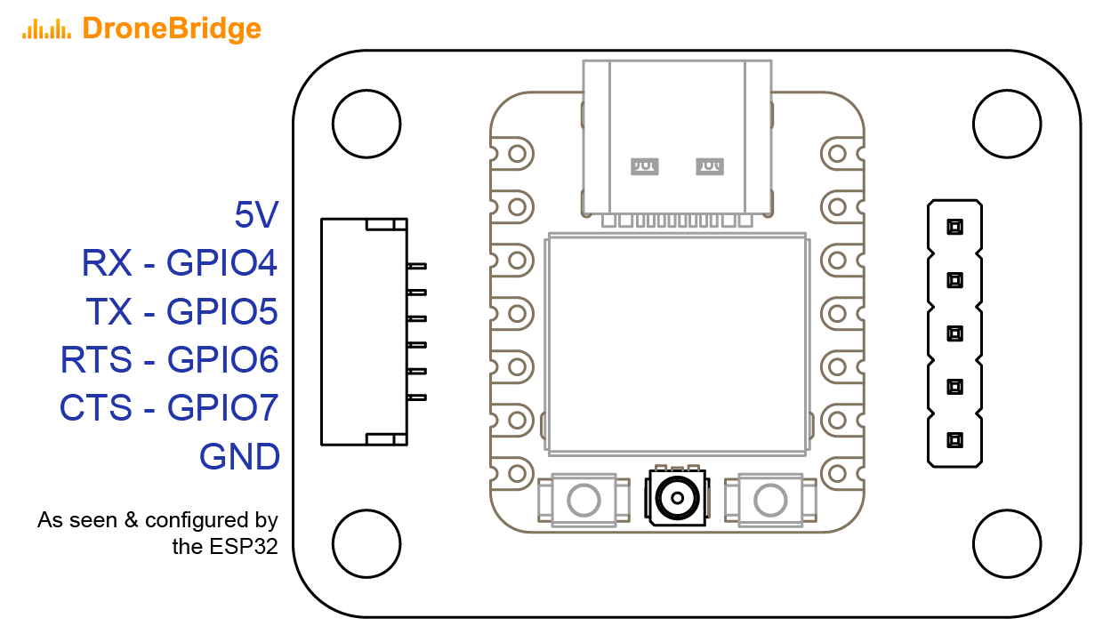
Pinout of the Official DroneBridge for ESP32 Hardware board featuring the ESP32C3
XIAO ESP32C3 to Pixhawk standard connector wiring
XIAO ESP32C6 to Pixhawk standard connector wiring
| Chip | Pins that do not work with DroneBridge |
|---|---|
| ESP32 | GPIO0, GPIO2, GPIO5, GPIO12 (MTDI), and GPIO15 (MTDO) GPIO6-11 and GPIO16-17 are usually connected to the SPI flash |
| ESP32-C3 | GPIO2, GPIO8 and GPIO9 GPIO12 ~ GPIO17 are usually used for SPI flash |
| ESP32-C5 | GPIO2, GPIO7, GPIO25, GPIO27, and GPIO28 GPIO16 ~ GPIO22 are usually used for SPI flash |
| ESP32-C6 | GPIO4, GPIO5, GPIO8, GPIO9, and GPIO15 GPIO24 ~ GPIO30 are usually used for SPI flash |
Wiring concept for the official DroneBridge for ESP32 hardware
Wiring concept for generic ESP32 hardware
DroneBridge for ESP32 with an external FTDI/USB-to-Serial adapter wired to the TELEM1 port for useage as a receiver on the Ground Control Station (GCS). An external RP-SAM antenna gives more freedom regarding reception. Case is 3D printed using FFF.